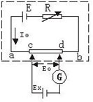
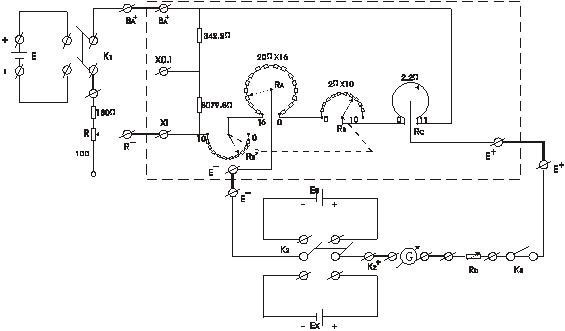
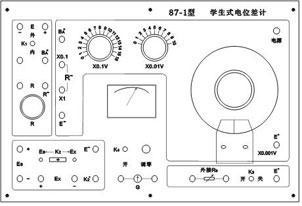
GT87-1 Student Potentiometer User's Manual The main purpose: The student-type potentiometer is designed according to the circuit of the series-connected potentiometer. It is characterized by simple circuit and clear principle. It is very suitable for students' experiments in universities, technical secondary schools and middle schools. It can not only directly measure the power electromotive force and temperature difference. Electromotive force, and can be used to measure DC current and resistance after using a standard resistor box. Main features: 1. The basic error of the potentiometer is ±0.2% (calculated by full scale value); 2. The working current of the potentiometer is 5.5 mA; 3. This potentiometer has the second gear ratio of “×1†and “×0.1â€; The upper limit of the "×1" file is 1.710 volts and the minimum index is 0.0001 volts; The upper limit of the “×0.1†is 171.0 mV and the minimum division is 0.01 mV. 4. This potentiometer can be used in an environment where the temperature is 0 to +35 ° C and the relative humidity is not more than 80%. 5, the working power of the potentiometer is 2.8 ~ 3.2 volts, can be directly used DC regulator source or A battery. At this time, the working current adjustment of the power circuit can use "internal R", when using 4 ~ 6 volts DC stabilized When the voltage source is used, an external resistor box can be used for working current regulation. I. Overview The potentiometer measures the unknown voltage or the unknown power source electromotive force by comparing the measured voltage with the internally known compensation voltage. When the compensation voltage and the measured voltage are balanced, the potentiometer does not draw current from the circuit under test. It also does not give current, thus ensuring the state of the circuit under test. This is the advantage and characteristics of the compensation method. Potentiometers are widely used in metrology and other precision measurements. 3. The difference meter experiment can understand the basic principle, structure and usage of the potentiometer. Second, the principle of potential compensation The voltmeter cannot accurately measure the electromotive force. The voltmeter can measure the voltage of each part of the circuit, but cannot measure the electromotive force of the power supply with internal resistance. Because the voltmeter is connected in parallel at both ends of the power supply (Fig. 1), according to the closed Ohm's law The indication of the voltmeter is the terminal voltage of the power supply at this time, not its electromotive force. In the figure: V=E-Ir E - power supply electromotive force; r - power supply internal resistance; I - current in the loop; V - voltmeter indication number; The indication number V of the voltmeter indicates the terminal voltage of the power supply; Ir is the voltage drop on the internal resistance of the power supply. Since the internal resistance of the power supply is unknown, the above formula cannot accurately determine the electromotive force of the power supply according to the value of V. figure 2 2 is a power supply Ex of the measured electromotive force and a known electromotive force of the power supply EO "+" end to the "+" end, the "-" end to the "-" end of the first circuit, a series galvanometer in the circuit "G", if the two power supply electromotive forces are not equal, that is, Ex≠E0, there must be current in the loop, the galvanometer pointer is deflected; if the electromotive force E0 is adjustable and known, then change the size of EO so that the circuit meets EX=E0, Then there is no current in the loop, and the galvanometer indicates zero. At this time, the electromotive force EX to be measured is completely compensated by the known electromotive force E0. The EX can be determined according to the known electromotive force value E0. This method is called the compensation method. The voltage between two points in a circuit, just need to connect the two points of the voltage to be tested The above compensation circuit replaces Ex, and its size can be measured according to the compensation principle. We know that when measuring voltage with a voltmeter, it is always necessary to separate a part of the current from the circuit under test, thereby changing the state of the circuit under test, and compensating When the voltage is measured, there is no current in the compensation circuit, so it does not affect the state of the circuit under test. This is the biggest advantage and feature of the compensation measurement method. Third, the potentiometer The instrument for measuring the electromotive force according to the principle of voltage compensation is called the potentiometer. It can be known from the above compensation principle that the measurement of the electromotive force by the compensation method should have two requirements for E0: (1) Adjustable. E0 and EX can be compensated. (2 Accurate. It can easily and accurately read the compensation voltage E0, the value should be stable. It is the principle circuit of the compensation method to measure the electromotive force, that is, the principle diagram of the potentiometer. The precision resistor Rab is used to form the voltage divider, and then the voltage-stabilized power supply E and the current limiting resistor R are connected in series to supply power to it. As long as the Rcd and I0 values ​​are used. Precisely, the voltage between cd in the dotted line in the figure is the accurate adjustable compensation voltage E0, and the loop cdGEX composed of E0 and EX is called the compensation loop. image 3 Fourth, the standard of potentiometer To make the operating current of the loop equal to the standard value I0 specified in the design, the potentiometer must be calibrated. The method is shown in Figure 4. The ES is a known standard electromotive force. According to its size, the resistance between cd is Rcd. Let Rcd=ES/I0, turn switch K back to ES, adjust R to make the galvanometer pointer have no deflection, and the circuit will be compensated. At this time, I0 satisfies the relationship I0=ES/Rcd, because the known ES and Rcd are quite accurate. , so I0 is accurately calibrated to the standard value, it should be noted that R can not be adjusted when measuring, otherwise the working current is no longer equal to I0. Figure 4 V. Measuring unknown electromotive force EX In Figure 4, the switch K is reversed to EX, keeping R unchanged, that is, I0 is unchanged. As long as EX ≤ IORab, adjusting c and d will definitely find a position, so that the galvanometer is again free of deflection, then c, d The resistance between them is RX, and the voltage is EX = I0RX. Because the actual potential difference meter converts the value of the resistance into a voltage value on the potentiometer, the value of EX=I0RX can be directly read from the surface scale. Six, student-type potentiometer The internal circuit of the student-type potentiometer is shown in the dotted line in Figure 5. The resistors RA, RB, and RC are equivalent to the resistor Rab in Figure 4. It can be seen that the two joints of BA+ and R- correspond to the two points of ba in Figure 4, E-E+ The two joints correspond to two points c and d. RA full resistance is 320 ohms, divided into 16 files, 20 ohms per gear; RB full resistance is 20 ohms, divided into 10 files, 2 ohm resistors per gear; RC is the sliding wire disk Resistance, resistance value is 2.2 ohm. RB resistance will change with the measurement file when measuring, which will inevitably cause the resistance change between a and b in Figure 4, destroying the constant regulation of the working current IO. Introduce RB's so-called replacement resistors. RB and RB' coaxial variations. Whenever RB increases the resistance of one gear, RB' decreases by one gear, and vice versa. Ensure that RB is in any gear, RB+ RB'= 20Ω is constant, ensuring that the total resistance between a and b in Figure 4 is constant. In order to implement the range conversion, a shunt branch is connected in parallel to the branch that produces the measurement compensation voltage. When ×1, the measurement compensation voltage branch is passed. The current is 5mA, the shunt branch current is 0.5 mA; when ×0.1, the current flowing through the compensating voltage branch is 0.5 mA, and the current flowing through the shunt branch is 5 mA. Obviously, the latter range is reduced to a very small amount due to the current. One, the range becomes very small. Figure 5 When using the student potential difference timer, an external circuit must be added, as shown in Figure 5. RA, RB, RC (from c to d) and the external circuit galvanometer G, protection resistor Rb, etc. constitute a compensation loop. K1 is the power supply Switch, K2 can keep ES and EX replaced quickly, K3 is the switch of galvanometer, Rb is variable resistance box to protect galvanometer and standard battery. Image 6 The required components of the external circuit of the student type potentiometer, except for the power supply E, the standard battery and the Rb variable resistance box, are all installed in the same wooden box, and the connecting wires between the parts are also supplied. Seven, the experimental content The content of this experiment is based on the experimental requirements specified in the "General Physics Experiment Lecture" prepared by the Physics Group of the Central Radio and Television University. The brief description is as follows: 2, measuring the battery electromotive force (called measurement) According to the approximate value of the electromotive force to be measured, RA, RB, and RC are placed. Rb takes the maximum value first, and K2 pushes to EX and simultaneously adjusts the potentiometers RA, RB, RC, and Rb to make the galvanometer have no deflection (in the step of measuring EX) Can not be changed) At this time, the reading values ​​displayed by RA, RB and RC are EX values, and K1, K2, K3 should be turned on at the end of the test. Repeat the two steps of “calibration†and “measurementâ€. The EX is measured three times, and the average value of EX is taken as the measurement result. by Simplified Where: r—battery internal resistance, Ω; EX—Battery electromotive force, V; E'- K4 closes the terminal voltage, V; R'—resistance of the resistance box in parallel with the battery, Ω. R' is known, as long as the voltages EX and E' at both ends of the ab when the switch K4 is opened and closed are respectively measured, and then substituted into the formula to obtain the internal resistance of the battery. Eight, matters needing attention 1. With the seven connections of the product as the thick line in Figure 5, when the "calibration" is performed, the short-circuit line is removed. When the instrument is not used, the galvanometer must be short-circuited. Otherwise, the test is performed. The flow meter is in an open state. 2. When using the potentiometer, the other circuit must be connected first, and then the compensation circuit should be connected. When the power is off, the compensation circuit must be disconnected before disconnecting other circuits. 3, the standard battery can only pass a current of about 1μA for a short time, otherwise it will affect the accuracy of the standard battery until the permanent electromotive force declines. Therefore, the calibration should pay attention to the use of "Rb", use K2 to be short, to protect the standard battery, can not Use volts to measure its electromotive force to prevent standard battery vibration. Figure 7 The battery to be tested cannot supply a large current, so the R' value when measuring the internal resistance should not be too small. R'=100Ω should be determined first and then the road should be connected. In the experiment, the switch K4 is closed only when measuring E ', and the measurement is completed immediately after disconnection, so as to avoid excessive discharge of the dry battery. 9. Instruments used in conjunction with this experiment (sold separately) 1, Rb variable resistance box - ZX21a type DC resistor, accuracy 0.1, measuring range 0 ~ 111111 ohms. 2, ES standard battery - BC2 portable saturated standard battery, accuracy 0.005, the actual value: 1.01855 ~ 1.01868 volts. Ten, complete set 1. GT87-1 student type potentiometer 1 set 2, the instruction manual 1 3, product certification 1 4, test the connection line 8 Under the conditions of the user's custody and use rules, the factory will repair the user for free within 12 months from the date of shipment from the manufacturer due to poor product quality or normal operation.
Our company is a professional manufacturer and exporter of a variety of handicrafts. Our company has been highly commented and trusted by the worldwide business partners for the diversity and high quality of our distinctive products in the past years.
Big Gear Wall Clock is very popular in Europe.Gear Wall Clocks are amazing for both home decor and office decor. Gear wall clocks are working with silence movement.Only need battery supported, much energy-efficient.
Our business principle is "quality good, favorable price, timely delivery and top service".
Gear Wall Clocks Gear Wall Clock,Extra Large Clock,Oversized Black Wall Clock,Big Clocks For Living Room Guangzhou Huan Yu Clocking Technologies Co., Ltd. , https://www.mk-times.com figure 1


If you want to measure the potential difference between two points in any circuit, just replace the EX with the two points to be tested. In this case, note that the high potential of these two points should replace the positive pole of EX, and the low replacement. negative electrode.
The potentiometer is an instrument that measures the electromotive force by the compensation method. In addition to the advantages of the general comparison method, when the unknown electromotive force EX is compared with the compensation voltage EO through the compensation circuit, the current is not taken from the EX, and the current is not input to the EX. Therefore, the power to be tested can be kept in the original state without interference from measurement. This is called in-situ measurement. The advantages of the potentiometer can be expressed as follows:
(1) The "internal resistance" is high and does not affect the circuit to be tested. When measuring the unknown voltage with the voltmeter, a part of the current is always separated from the circuit under test, which changes the working state of the circuit under test, and the internal resistance of the voltmeter is smaller. The more obvious this effect is, when measuring with a potentiometer, the current in the compensation loop is zero, and the true voltage at both ends of the circuit can be measured.
(2) Accuracy. Since the resistance Rab can be made very precise, the electromotive force of the standard battery is accurate and stable, and the galvanometer is sensitive enough, so it can provide a fairly accurate compensation voltage under the compensation condition, and the potential difference is commonly used in the measurement work. Count to calibrate the meter.
It is worth noting that during the measurement process, the working condition of the potentiometer will change (such as the loop power supply E is unstable, the current limiting resistor R is unstable, etc.), in order to ensure that the current maintains the specified value, each measurement must pass There are two basic steps of calibration and measurement. The interval between the two basic steps should not be too long, and each time the compensation is to be adjusted carefully, so the operation is complicated and time consuming. 

1, calibration student type potentiometer (called calibration)
Before using the potentiometer, first calibrate to make the current reach the specified value. Put RA, RB and RC first, make the voltage scale equal to the standard battery electromotive force, take off the short circuit on the galvanometer, and use the attached wire to K1 , K2, K3, G, R, Rb and potentiometers are connected according to the principle circuit diagram. After repeated inspections, the working power supply E, the standard battery ES and the electromotive force to be tested EX, Rb are taken first. The maximum value of the resistance box. (If the galvanometer is unstable during use, the value can be reduced until the galvanometer is stable.) Close K1 and K3, push K2 to ES (intermittent use), and adjust at the same time. R, the galvanometer is not deflected (refer to zero), in order to increase the galvanometer sensitivity, the Rb should be gradually reduced, so repeatedly open and close K2, confirm that no current flows in the galvanometer, then IO has reached the specified value.
3. Measuring the internal resistance of the battery
a, open K2, K3 replace the EX in Figure 5 into the line shown in Figure 7, the rest is unchanged, R' is the resistance box.
b. With the above measurement steps, close K4 and measure R', the voltage at both ends E'. 


