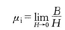
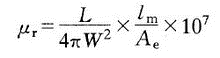
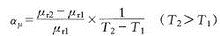
Permeability is a physical noun that represents the physical quantity of magnetic properties of a magnetic medium. Introduction The magnetic permeability μ is equal to the ratio of the differential of the magnetic induction B in the magnetic medium to the differential of the magnetic field strength H, ie μ=dB / dH Generally used is the relative magnetic permeability μr of the magnetic medium, which is defined as the ratio of the magnetic permeability μ to the vacuum magnetic permeability μ0, that is, μr=μ/μ0 The relationship between the relative magnetic permeability μr and the magnetic susceptibility χ is: μr=1+χ The magnetic permeability μ, the relative magnetic permeability μr and the magnetic susceptibility χ are physical quantities describing the magnetic properties of the magnetic medium. For the paramagnetic mass μr>1; for the antimagnetic mass μr<1, but the μr of both are almost the same as 1 . In most cases, the relative permeability of the conductor is equal to 1. In ferromagnetic properties, the relationship between B and H is a nonlinear hysteresis loop, and μr is not a constant, and is related to H, and its value is much larger than 1. For example, if the relative magnetic permeability of air (non-magnetic material) is 1, the relative magnetic permeability of the ferrite is 10,000, that is, when compared, the magnetic flux density through the magnetic material is 10,000 times. The cast iron is 200~400; the silicon steel sheet is 7000~10000; the nickel zinc ferrite is 10~1000. formula Energy density of magnetic field = B^2/2μ In the International System of Units (SI), the relative magnetic permeability μr is a dimensionless pure number, and the unit of magnetic permeability μ is Henry/meter (H/m). Commonly used vacuum permeability Common parameters (1) Initial permeability μi: refers to the magnetic permeability of the basic magnetization curve when H→0 formula (2) Maximum magnetic permeability μm: After the initial period of the basic magnetization curve, the slope μ=B/H gradually increases with the increase of H, and reaches a maximum value under a certain magnetic field strength (Hm). Bm), that is, (3) saturation magnetic permeability μS: the magnetic permeability of the saturation section of the basic magnetization curve, the μs value is generally small, and when deep saturated, μs = μo. (4) Differential (incremental) magnetic permeability μ Δ: μ Δ = ΔB / ΔH. ΔB and ΔH are the increments taken at the point (B1, H1) as shown in Figs. 1 and 2. (5) Differential magnetic permeability, μd: μd = dB / dH, and the differential is obtained at the (B1, H1) point to obtain μd. It can be seen that μ1=B1/H1, μ△=ΔB /ΔH, μd=dB1/dH1, although the magnetic permeability at the same point is not equal in value. Non-magnetic materials (such as aluminum, wood, glass, free space) B to H ratio is a constant, using μ. To indicate the magnetic permeability of the non-magnetic material, that is, μ. =1 (in the CGS unit system) or μ. = 4Ï€X10o-7 (in the RMKS unit system). Among many materials, if the free space (vacuum) μo=1, then the material slightly larger than 1 is called paramagnetic material (such as platinum, air, etc.); the material slightly smaller than 1 is called diamagnetic. Materials (such as silver, copper, water, etc.). The magnetic element μ1 introduced in this chapter is very useful. Only when magnetic shielding is required, the shielding material is made of a diamagnetic material such as copper so that the magnetic properties of the magnetic element are not radiated into the space. Here are a few common paradigms: formula (1) Effective magnetic permeability μro. In the closed magnetic circuit formed by the inductor L (the leakage flux is negligible), the effective magnetic permeability of the core is: The self-inductance (mH) of the L--winding in the formula; W--winding turns; The core constant is the ratio of the magnetic path length Lm to the core cross-sectional area Ae (mm). (2) Saturation magnetic induction Bs. As the magnetic field strength H in the core increases, the B value at which the magnetic induction intensity appears saturated is called the saturation magnetic induction B. (3) Residual magnetic induction Br. The remaining magnetic induction (or residual flux density) after the magnetic core removes the magnetic field from the magnetic saturation state. (4) Coercivity Hco. After the magnetic core removes the magnetic field from the saturated state, the reverse magnetization is continued until the magnetic induction intensity is reduced to zero, and the magnetic field strength at this time is called coercive force (or coercive force). formula (5) Temperature coefficient aμ° The temperature coefficient is the relative change of the corresponding magnetic permeability for each change of 1 °C when the temperature changes within the range of T1~T2, ie Where μr1--the magnetic permeability when the temperature is T1; rr2--The magnetic permeability at a temperature of T2. It is worth noting that in addition to the magnetic permeability μ and temperature, the magnetic parameters such as saturation magnetic induction Bs, residual magnetic induction Br, coercive force Hc, and core specific loss Pcv (unit weight loss W/kg) are also Both are related to the operating temperature of the core. Features The measurement of magnetic permeability is indirect measurement, the inductance of the winding coil on the core is measured, and the magnetic permeability of the core material is calculated by the formula. Therefore, the magnetic permeability test instrument is the inductance tester. It is emphasized here that some simple inductive test instruments cannot be adjusted in test frequency and the test voltage cannot be adjusted. For example, some bridges have a test frequency of 100 Hz or 1 kHz and a test voltage of 0.3 V. This 0.3 V is not the voltage across the inductor, but the voltage generated by the signal generator. As for the voltage across the coil under test is an unknown number. If you use a high-end instrument to measure inductance, such as the Agilent 4284A precision LCR tester, not only the test frequency is adjustable, but also the voltage and magnetizing current across the measured inductor coil are adjustable. Understanding these features of the test instrument can be a great help for the correct measurement of magnetic permeability. Method principle Speaking of the measurement of magnetic permeability μ, it seems very simple, just a few coils around the material sample ring, measuring its inductance, find a formula is complete. In fact, for the same sample loop, different instruments, different voltages, different voltages or different frequencies may be used to measure the magnetic permeability that is far different. The reason for the great difference in test results is that not every tester has the energy to make it clear. This paper mainly discusses the influence of different test parameters and calculation formulas on magnetic permeability measurement. 2.1 Influence of calculation formula As we all know, the method of measuring the magnetic permeability μ is generally to measure the inductance L around the N åŒ coil on the sample loop, because the expression that can be derived from L is: L=μ0 μN^2A/l (1) Therefore, the formula for calculating the permeability from (1) is: μ=Ll/μ0N^2A (2) Where: l is the magnetic path length of the core, and A is the cross-sectional area of ​​the core. For a toroidal core with a rectangular cross section, if its average magnetic path length l = Ï€ (D + d) / 2 is taken as the magnetic path length l of the core, the sectional area A = h (Dd) / 2, 00=4π×10-7 are substituted into (2): μ=L(D+d)*10/4Nh(Dd) (3) Where D is the outer diameter of the ring, d is the inner diameter, and h is the height of the ring, as shown in FIG. Substituting the inner diameter d=D-2a of the ring into equation (3): μ=L(Da)*10/4Nha (4) Where: a is the wall thickness of the ring. For a toroidal core with a smaller inner diameter, the inner diameter is not as easy to measure as the wall thickness, so it is convenient to use the type (4). Equations (4) and (3) are equivalent, and their origin is to take the average magnetic path length of the ring as the magnetic path length of the core. The magnetic permeability calculated from them is called the ring magnetic permeability of the material. Some people say that the magnetic permeability measured by a ring sample is called ring magnetic permeability. This is not true. In fact, the ring permeability is higher than the actual magnetic permeability of the material, and the thicker the wall of the sample ring, the greater the error. For the sample ring, the magnetization field is non-uniform in the radial direction under the same ampoule magnetomotive force excitation. The closer to the outer side of the ring wall, the weaker the magnetic field. Under the condition that the magnetic permeability μ is constant throughout the sample ring, the closer to the outer side of the annular wall, the lower the magnetic flux density B of the ring. In order to eliminate the influence of this uneven magnetization on the measurement, we consider the sample ring to be composed of an infinite number of thin-walled rings with a radius r and an infinite thickness of dr. According to formula (1), the inductance dL produced by each thin-walled ring can be written as: (5) From (5), the integral r is integrated from the inner radius r1 to the outer radius r2, and the inductance L generated by the entire sample ring is obtained: (6) The exact formula for calculating the magnetic permeability derived from equation (6) is: (7) In order to facilitate practical application, (7) can be converted into; (8) In the above formula: D is the outer diameter of the sample ring, and d is the inner diameter. Converting the natural logarithm to a common logarithm, (8) is transformed into: (9) If the sample ring is composed of the same material, the magnetic permeability calculated by the formula (7), (8) or (9) is the true magnetic permeability μ of the material. It is slightly lower than its ring permeability. 2.2 Test the influence of the number of turns of the coil N Since the inductance L is proportional to the number of turns N2, it is reasonable to say that the magnetic permeability μ calculated by the formula (9) should not be related to the number of turns N, but it is often related. Regarding the measurement of the magnetic permeability of materials, the test frequency generally used is not high, and is often tested at a frequency of 1 kHz or 10 kHz. The test signal is generally a sinusoidal signal, because the frequency is not high, the resistance part of the sample surrounding the coil impedance is negligible, and the winding coil is regarded as a pure inductance L connected to the measuring instrument. The test equivalent circuit is shown in the figure. The effective value of the voltage generated by the instrument signal source is U, and Ri is the output impedance of the signal source. The expression of magnetizing current is easily written by Figure 3: (10) In the above formula, ω is the angular frequency of the instrument signal source, and L is the inductance of the sample surrounding coil. L=μ0μN2Ae /le (11) In (11), Ae is the effective sectional area of ​​the core, and le is the effective magnetic path length of the core. If the Ae and le of the ring core are substituted, the equation (11) becomes the same as the result of the equation (6). The effective magnetic field strength peak Hm produced by the test current is: (12) Substituting (10) and (11) into (12) gives: (13) It can be seen from equation (13) that when (ωμ0μAe) 2N4 is much smaller than le2Ri2, the equation (13) can be approximated as: (14) The above formula tells us that when the number of turns of the test coil is small, the strength of the test magnetic field is proportional to the number of turns. As the number of turns increases, when (ωμ0μAe) 2N4 is much larger than le2Ri2, the equation (13) can be approximated as: (15) It can be seen from equation (15) that when the number of turns of the test coil is too large, the strength of the test magnetic field is inversely proportional to the number of turns. From the above analysis, when measuring the magnetic permeability, the magnetization field strength in the sample loop is related to the number of turns of the test coil, and when the number of turns is a certain value, the magnetic field strength reaches the strongest value. The magnetic permeability of the material is closely related to the magnetization field strength, so the measurement of the magnetic permeability is related to the number of turns of the test coil. The effect of the number of turns on the permeability test is discussed in detail in conjunction with the figure. 2.2.1 When the test voltage U is low As mentioned earlier, for high-end instruments, such as the Agilent 4284A precision LCR tester, its test voltage can be adjusted so low that the test magnetic field strength is the strongest with the change in the number of turns, and there is still no magnetic permeability. Start area. At this time, the initial permeability μi of the material is always measured, which is independent of the number of turns of the test coil. With the same instrument, if the test voltage is adjusted to a high level, it can no longer be guaranteed that the magnetic permeability measured by different turns is the initial permeability, and the measured magnetic permeability will be compared with the test coil turns. It’s related. 2.2.2 Test voltage U can not be adjusted Most simple instruments that measure inductance cannot be flexibly adjusted in terms of test voltage and frequency. For example, the 2810 LCR bridge has a test frequency of 100 Hz or 1 kHz and a test voltage of less than 0.3V. Jasmine Essential Oil,Rose Oil For Skin,Rose Massage Oil,Flower Blend Essential Oil Ji'An ZhongXiang Natural Plants Co.,Ltd. , https://www.zxnaturaloils.com