Bamboo Golf Tees,Bamboo Castle Golf Tees,Personalised Bamboo Golf Tees,Golf Tees Bamboo Nanchang Sou Bamboo Network Technology Co., Ltd. , https://www.168bamboo.com
The RF signal modulation methods between the RF card and the reader are commonly FSK (frequency modulation), PSK (phase modulation), BIPH (biphase), Manchester (Manchester). Among them, the Manchester modulation method is generally used in low-frequency, low-cost products. Although IC cards modulated by Man code in foreign countries are not commonly used, due to its low price, the low-end ICs using this modulation method in China are currently used. Cards also have a wide range of applications. In practical applications, users sometimes encounter the problem of decoding Manchester coding. In view of this, this paper introduces a decoding method for the reader's reference.
1 Overview of Radio Frequency Identification (RFID) Technology
1.1 The basic working principle of the RFID system
Radio frequency identification (RFID) technology is a non-contact automatic identification technology. The basic principle is to use space electromagnetic induction or electromagnetic propagation to communicate, so as to automatically identify the target object and obtain relevant data.
The RFID system consists of two parts: a radio frequency card and a radio frequency card reader. As shown in Figure 1, the space (contactless) coupling of the RF signal is realized by the coupling element between the RF card and the reader, in the coupled channel, according to the timing. Relationships, energy transfer and data exchange. 
In practical application hardware circuits, the reader/writer generally consists of an antenna, a base station chip, and an MCU. Among them, the base station chip mainly implements the function of the high-frequency interface module, and is used for completing data modulation, transmission, radio frequency reception, and data demodulation tasks.
The following briefly introduces a radio frequency card base station chip U2270B. U2270B is a radio frequency card base station chip capable of reading and writing the IC card. The main features are as follows:
The oscillator can generate a carrier frequency of 100kHz ~ 150kHz, and can be precisely adjusted by an external resistor, its typical application frequency is 125kHz;
Suitable for Manchester coding and bi-phase coding;
With a microprocessor interface, can be directly connected to the microcontroller;
The typical read and write distance at 125 kHz is 15 mm.
In practical applications, when the RF card enters the RF field generated by the reader antenna, it is triggered by the action of electromagnetic induction, and the load modulation signal sent from the RF card will generate a weak amplitude modulation on the base station antenna. The base station chip can recover the RF card modulated data stream. It should be noted that when the returned RF card modulated data stream is in Manchester encoding format, the U2270B outputs a standard Manchester encoded signal compatible with the MCU interface to the MCU through a series of internal processing, and the U2270B cannot perform Manchester encoding demodulation. The demodulation work must be done by the MCU software, which is what this article means.
1.3 RF card
There are many classification methods for RF cards, of which three types can be divided into chips: read-only cards, read-write cards and CPU cards.
The following describes a read-only card (also known as ID card) EM4100, which senses power supply by the reader and reads out the unique card number stored in the chip EEPROM. The card number is written once before the package, and cannot be changed after the card is sealed.
The main features of the EM4100ID card:
The carrier frequency RF is 125 kHz;
The sensing distance is 2 to 15 cm;
A total of 64 data storage capacity, including manufacturer, release number and user code;
The data transmission rate is RF/64bit/s, RF/32bit/s and RF/16bit/s.
In-card data format: a total of 64 bits, including 9 start bits, 40 data bits (the first 8 bits are version or manufacturer information, the last 32 bits are user information), 10 rows of check digits, 4 columns Check digit, 1 end stop bit.
When the reader is in the working state, when the ID card enters the RF field generated by the reader, the 64-bit data in the card is cyclically outputted until the ID card leaves the reader and loses power.
2 Manchester decoding software design
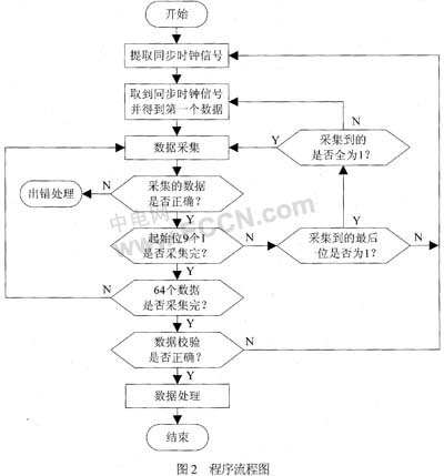
If the EM4100 ID card is decoded, the carrier frequency RF is 125 kHz, and the data transfer rate is RF/64, then the clock period required to transmit one bit of data is T = 512 μs. First, since the Manchester code contains the synchronous clock signal, the first step must extract the synchronous clock signal and, when the synchronous clock signal is extracted, the first data will be obtained. After that, data can be collected. In the data acquisition, the first 9 bits of the start bit are collected, and the subsequent data is collected. Then perform parity and some processing on the data. The flow chart of the program is shown in Figure 2. 
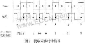
Manchester coding generates a transition in the middle of the bit period, so the synchronous clock signal can be extracted by detecting the rising or falling edge of the Manchester code by: between the first rising edge (or falling edge) detected by the program. If a low level (or high level) of t = T' (T' is the time required to transmit one bit of data, ideally a bit clock period T) is detected, then this rising edge (or falling edge) Must occur in the middle of the bit clock cycle. When the synchronous clock signal is obtained, the first data bit 1 (or 0) will be obtained, and the currently received data bit will be stored in the memory of the microcontroller, and this will be simultaneously The value is assigned to a status bit con_receive=1 (or 0), which is used when detecting the next data. Taking Figure 3 as an example (in this case, the synchronous clock signal is extracted by the rising edge), before the rising edge of b, the low level with t=T' time is detected, then the rising edge of b must be generated in the middle of the bit clock period. At the same time, the first data 1 is obtained, the data 1 is stored in the register, and the status bit con_receive=1 is used for the detection of the next data.
2.1 Data collection
After the synchronous clock signal is extracted, the data can be extracted by detecting the time interval between two rising edges (or falling edges). The time interval between the two rising edges (or falling edges) has a total of t=T', t=1.5T', and t=2T'.
If the interval t=T' between the two rising edges is detected, then a data identical to the previous logical value is received, such as Figure 3, detected at c at time t=T' after the rising edge of b The rising edge gives the same data 1 as the previous logical value con_receive. This data is stored in the memory, and the current logical value 1 is assigned to the status bit con_receive; if the time interval between two rising edges is detected as t=1.5T', two cases: the current data value con_receive is At 1 o'clock, two data 00 are obtained, and the logical value 0 is assigned to con_receive; when the current data is 0, a data 1 is obtained, and the logical value 1 is assigned to con_receive. As shown in Figure 3, a rising edge is detected at d at the time t = 1.5T' after the rising edge of c. Since the logical value obtained at the rising edge of c is 1, the data 00 is obtained, and the value of con_receive is also changed to 0; After T' time, it reaches the rising edge of e, and gets the same data 0 as the previous logic value; after t=1.5T' time, it reaches the rising edge of f. Since the logical value of the previous data is 0, the data is obtained, con_receive It also becomes 1; if a time interval t=2T' between two rising edges is detected, two data 01 are obtained, and a logical value of 1 is assigned to con_receive. As shown in Figure 3, a rising edge is detected at g of t = 2T' time after the rising edge of f, resulting in two data 01; 
In the process of collecting data, due to some interference or other factors, the data acquisition error can not be avoided, and the error processing part can be decided by the reader himself. For example, you can choose to restart the extraction of the synchronous clock signal and re-decode. If you have not obtained 64-bit data after a certain number of consecutive re-decoding, you will be alerted.
2.2 Data verification and data processing
In order to facilitate the parity check of the read data, 55 data after the start bit of 9 are stored as one byte every 5 bits. After the data is completely read, according to the data structure of the ID card, Parity the data. After the parity is correct, the raw data can be further processed for experimental application.
2.3 Other notes
In an ideal state, the time T' of transmitting one bit of data should be equal to the bit clock period T. Because of the strength of the RF field signal and the influence of the outside world, T' is not a stable value, so in practical applications, T' is a Ranges. For example: when the bit clock period is T=512μs, ideally, T'=T=512μs, but in reality T' selects a range, for example, 400μs<T'<580μs, 640μs<1.5T'<820μs, 870μs<2T'<1100μs (These values ​​are not fixed and are not too strict. In practical applications, it is best to measure the ID card used and then select the result from the measurement.
Some ID card Manchester code is bit data 1 corresponding to the level lower bit, bit data 0 corresponds to the level jump, when decoding this card, as long as the detection of the rising edge in the program becomes the detection falling edge, detecting the falling edge It becomes ready to detect the rising edge.
The rising edge (or falling edge) can be detected by an interrupt method or a scanning method. When the scanning method is adopted, since the data signal is affected by various effects of modulation, demodulation, and noise in actual operation, there are jitters on the rising edge and the falling edge, and the jitter can be eliminated by using a keyboard to eliminate the jitter.
If the parity has not been correctly 64-bit data after a certain number of consecutive NGs, it can be handled by an alarm or other means.
At present, with the development of technology and the needs of applications, IC cards (also known as smart cards) have been widely used in people's daily lives. Generally, an IC card can be classified into a contact type IC card and a contactless type IC card. The contact IC card is a direct physical contact between the card and the card reader for data exchange, and some metal circuits are exposed outside, such as a mobile phone card, a public IC phone number, and the like. The non-contact IC card is also called a radio frequency card, and the data exchange between the radio frequency and the card reader through the radio frequency signal does not require physical contact, and the circuit is packaged inside, such as a toll card of the bus. Compared with contact IC cards, non-contact IC cards have only high reliability, are easy to use, and are not afraid of rain, static electricity, and no contact scratches. Therefore, they have been widely used. The technology used in such contactless IC cards is called RFID technology.