Keywords: stripe OTP failure Krause mirror oscilloscope multimeter method When the LSJET platform type CTP plate-making machine works, the printing plate remains stationary, and the exposure head moves horizontally along the X-axis direction driven by the screw. The laser beam scans in the Y-axis direction line by line under the high-speed rotation of the eight prisms. Each time the eight prisms rotate one face, the laser beam forms a scanning line formed by a plurality of scanning points on the printing plate (scanning points The number is related to the resolution of the CTP). The eight prisms go to the next face, and the laser beam starts scanning again from the starting position of the next line. The eight prisms rotate one revolution, and the laser beam forms eight lines of scanning lines on the plate. An image dot consists of several adjacent scan points that are not on the same line. The starting position of the scanning point is controlled by a SOS (START SCAN SENSOR) sensor, which determines that each line of the laser beam starts scanning from the same starting position. The machine's high mechanical accuracy and reliable transmission of scanned data ensure that the scanning points are arranged in a straight line along the Y-axis; the arrangement of scanning points in the X-axis direction (the direction of movement of the exposure head) is controlled by the CSU (CROSS SCAN UNIT) sensor. A given condition (such as temperature) is also arranged in a straight line. When a given condition changes, the feedback voltage of the CSU sensor also changes, changing the arrangement of the scanning points in the X-axis direction. The CTP optical system consists of sophisticated and complex optical components. These optical components are sensitive to changes in temperature. Changes in the internal temperature of the machine cause small changes in its physical and optical properties. 10Pcs Alcohol Wipe,Small Alcohol Wipes,Alcohol Tissue Wipes,Alcohol Wet Tissue DONGYANG COMEXA SANITARY PRODUCTDS LTD.,CO , https://www.comexawipes.com
In order to better grasp the needs of the newspaper market, enhance market competitiveness, meet its growing business needs, and simultaneously reduce the entire printing process, especially prepress processing time, improve the timeliness of news and the printing quality of newspapers, Liberation Daily The Printing Center introduced two LaserStar JET computer direct-working systems manufactured by the German Krause Company.
In the process of using, for a certain period of time, the LSJET flatbed CTP production line has a stripe fault in the X-axis direction (ie, the horizontal movement direction of the exposure head) of the printing plate image portion, which affects the platemaking quality and the newspaper printing quality to some extent. With the help of Krause's technical staff, we solved the problem. The causes and exclusion methods of CTP streaks are now written out for reference by peers.
Causes of streaks
As we all know, CTP direct platemaking machine consists of three parts: optical system, circuit system, and mechanical system. The single-beam original laser generated by the laser is split into multi-beam (usually 200 to 500) ultrafine micro laser beams via multiple optical fibers or a complex high-speed rotating optical splitting beam system. According to the bright and dark features of computer graphic information, the acousto-optic modulator modulates the bright and dark changes of the micro laser beam to form a controlled beam. The controlled beam is then focused on the surface of the printing plate for exposure, forming a latent image on the plate. After development, the graphic information on the computer screen is restored to the plate.
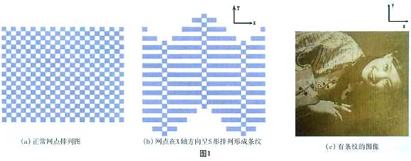
The image of the printing plate graphic is composed of dots, and the image quality is related to the dot size, shape, and arrangement position of dots. When the size and shape of the dot remain the same, the change in the dot arrangement has a great influence on the image quality. As shown in Figure 1, we use 50% of the dots as an example to illustrate the principle of image stripe formation. Figure (a) is a schematic diagram of the normal arrangement of the dots. The dots are arranged in a straight line in both the X-axis direction and the Y-axis direction. (b) is a schematic diagram of the image of the dots arranged in an S-shape in the X-axis direction. There are stripes in the direction. The image stripe failure in the X-axis direction of the CTP plate is caused by the S-shaped arrangement of the exposure spot in the X-axis direction when scanning the laser beam. See (c) for actual striped images. 
(to be continued)